Bending tables
8.1. Bending: Open sections and channels
(a) Design resistance of cross-section
The design resistances for bending about the principal axes of the cross-section are given by:
Code ref
§6.2.5 (2)
§6.2.8 (2)
(i) For Class 1, 2 cross-sections:
 |  |
(ii) For Class 3 cross-sections with a Class 1 or 2 flange:
 |
(iii) For other Class 3 sections
 |  |
(iv) For Class 4 cross-sections
 |  |
Note:
- Some I and H sections in S355 and S460 are Class 4 under bending alone. Although the effective section properties are not tabulated, effective properties have been used to derive the bending resistance tables.
- Where the design shear force is high ( > 50% of the shear resistance), a reduced value of resistance for bending M v,y,Rd and M v,z,Rd should be calculated. No values are tabulated in this website. Values of the design shear resistance Vc,Rd are given in the tables of web bearing and buckling resistance (see Section 9.1).
(b) Design lateral torsional buckling resistance moment
The lateral torsional buckling resistance moment M b,Rd is given in the tables for a range of values of the following parameters:
Code ref
§6.3.2
- The length between lateral restraints, L, given at the head of the tables
- The value of factor C1
The lateral torsional buckling resistance moment, M b,Rd, is given by:
Code ref
§6.3.2.1 (3)

where:
Code ref
§6.3.2.3 (1)
| W y | = W pl,y | for Class 1, 2 cross-sections |
| W y | = W pl,eff,y | for Class 3 cross-sections with Class 1 or 2 flanges |
| W y | = W el,y | for other Class 3 cross-sections, this includes Class 3 with Class 3 flanges |
| W y | = W eff,y | for Class 4 cross-sections |
| χ LT | is the reduction factor for lateral-torsional buckling. It depends on the non-dimensional slenderness  and the imperfection factor corresponding to the appropriate buckling curve. and the imperfection factor corresponding to the appropriate buckling curve. | |
| M cr | is the elastic critical moment for lateral-torsional buckling based on gross sectional properties and takes into account the following:the moment distributionthe length between lateral restraints. | |
| C 1 | is a factor that takes into account the shape of the bending moment diagram. Values of C 1 given in the tables include 1.0; 1.13; 1.35; 1.5; 1.77; 2.0 and 2.5. Elastic critical moment for lateral torsional buckling (Access Steel document SN003) [18] gives background information related to this factor. To take C 1 = 1.0 is conservative. | |
The C 1 values of 1.13, 1.35 and 1.77 correspond to common design situations, as shown below.
| Loading | Bending moment diagram | C 1 factor |
|---|---|---|
| UDL, pin-ended beam |  | 1.13 |
| Central point load, pin-ended beam |  | 1.35 |
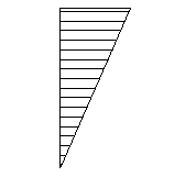
| Triangular bending moment diagram, pin at one end |  | 1.77 |
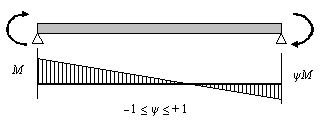
For linear bending moment diagrams, C 1 may be determined from the following table, based on ψ, the ratio of the end moments.
| End moment loading | ψ | C 1 |
|---|---|---|
 | + 1.00 | 1.00 |
| + 0.75 | 1.17 | |
| + 0.50 | 1.36 | |
| + 0.25 | 1.56 | |
| 0.00 | 1.77 | |
| - 0.25 | 2.00 | |
| - 0.50 | 2.24 | |
| - 0.75 | 2.49 | |
| - 1.00 | 2.76 |
For other shapes of bending moment diagram, the factor C 1 may be determined from the ratio:

M cr may be determined by using the software LTBeam, freely available from www.cticm.com
The reduction factor χLT is calculated for the 'rolled sections' case, using buckling curves "b" or "c" as appropriate and the values of  LT,0 and β given by the National Annex. The UK National Annex gives the following values:
Code ref
§6.3.2.3 (1)
 LT,0 LT,0 | = 0.4 |
| β | = 0.75 |
The reduction factor is modified to take account of the moment distribution between the lateral restraints of members using the modification factor f:
Code ref
§6.3.2.3(2) and the UK NA
 |
 |
 |