Member resistances
4.1 Design strength
Minimum value of design strengths in relation with thickness have been taken from EN 10025-3:2019, as follows:
| Design strength (N/mm2) for element thickness (mm) | ||||||
| Steel Grade | ≤ 16 | 16 < t ≤ 40 | 40 < t ≤ 63 | 63 < t ≤ 80 | 80 < t ≤ 100 | 100 < t ≤ 150 |
| S355 | 355 | 345 | 335 | 325 | 315 | 295 |
| S420 | 420 | 400 | 390 | 370 | 360 | 340 |
| S460 | 460 | 440 | 430 | 410 | 400 | 380 |
4.2 Cross section bending resistance, Mcy,Rd
The cross section bending resistance of Class1, 2 and 3 members is determined in accordance with EN 1993-1-1.
For Class 4 sections, a section modulus is not calculated. The neutral axis of the stress block is determined by equating tension and compression in the section, allowing for the effective area of the web, and limiting the stress in the web to the design strength. Once the position of the neutral axis has been determined, the cross sectional resistance in bending is determined from the product of the stress in an element, the area of the element and the lever arm appropriate for the element.
4.3 Shear resistance, VRd
4.3.1 Non-slender webs
For non-slender webs, the shear resistance of the section is calculated in accordance with EN 1993-1-1:2005 clause 6.2.6. The shear area of the web is given in clause 6.2.6(3)d.
4.3.2 Unstiffened slender webs
When  the shear buckling resistance is calculated in accordance with clause 5 of EN 1993-1-5. It is assumed that there will be a single bearing stiffener at each support, but that the ends will not be classed as a 'rigid endpost' for determination of the shear buckling resistance.
In calculating the shear buckling resistance, the contribution from the flange, as described in clause 5.4 of EN 1993-1-5:2006, is ignored.
Because the web panel is taken as the span of the member, the minimum shear resistance is calculated for the maximum tabulated span.
4.3.3 Stiffened webs
The resistance is calculated assuming an aspect ratio of 2.0 (i.e. a = 2hw). A non-rigid end post is assumed.
4.3.4 Flange induced web buckling
The web of each section is verified for this effect in accordance with section 8 of EN 1993-1-5.
4.4 Lateral torsional buckling resistance
The non-dimensional slenderness is calculated as:

Mcr is calculated based on the gross cross-section.
Lateral torsional buckling values are provided for a range of C1 values to aid interpolation. The following values of C1 cover specific shapes of bending moment diagram.
| Load arrangement | Bending moment diagram | C1 value |
| UDL | 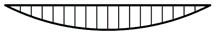 | 1.13 |
| Central point load, pinned ends | 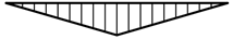 | 1.35 |
| Moment at one end, no intermediate loads, other end pinned | 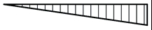 | 1.77 |
4.5 Weld design
No weld details are given in the resistance tables. Welds between the flanges and the web should be designed in accordance with EN 1993-1-5:2006 clause 9.3.5.
If the design shear VEd is less than the resistance of the web alone, given by  , the weld is to be designed for
  .
.
This is always the case for unstiffened girders when the web resistance has been based on the web alone, which is the approach taken in deriving the tabulated shear resistances.
If the applied shear is greater than the resistance of the web alone, the welds are to be designed for  , which is full strength in shear.
Welds should be designed in accordance with EN 1993-1-8 [6].