Section properties
3.1. General
All section properties have been accurately calculated and rounded to three significant figures. They have been calculated from the metric dimensions given in the appropriate standards (see Section 1.1). For angles, EN 10056‑1 [8] assumes that the toe radius equals half the root radius. For tapered flange channels the flange thickness, tf is the thickness at a distance u from the flange toe, with the association taper, as follows:
| h | u | Taper |
| ≤ 300 | b/2 | 8% |
| > 300 | ( b − tw )/2 | 5% |
3.2. Open sections
3.2.1. Second moment of area (I )
The second moment of area has been calculated taking into account all tapers, radii and fillets of the sections. Values are given about both the y‑y and z‑z axes.
3.2.2. Radius of gyration (i )
The radius of gyration is a parameter used in the calculation of buckling resistance and is derived as follows:
i = [I / A]1/2
where:
| I | is the second moment of area about the relevant axis |
| A | is the area of the cross section |
3.2.3. Elastic section modulus (Wel )
The elastic section modulus is used to calculate the elastic design resistance for bending or to calculate the stress at the extreme fibre of the section due to a moment. It is derived as follows:
W el,y = I y / z
W el,z = I z / y
where:
| z, y | are the distances to the extreme fibres of the section from the elastic y-y and z-z axes, respectively |
For parallel flange channels, the elastic section modulus about the minor (z‑z) axis is given for the extreme fibre at the toe of the section only.
For angles, the elastic section moduli about both axes are given for the extreme fibres at the toes of the section only. For elastic section moduli about the principal axes u‑u and v‑v, see AD340 [11].
3.2.4. Plastic section modulus (Wpl )
The plastic section moduli about both y‑y and z‑z axes are tabulated for all sections except angle sections.
3.2.5. Buckling parameter (U ) and torsional index (X )
I and H sections, and channels
The buckling parameter (U ) and torsional index (X ) have been calculated using expressions in Determination of non‑dimensional slenderness of I and H sections (Steelbiz document SN002 [16]).
U = 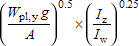
X = 
Where:
| W pl,y | is the plastic modulus about the major axis |
| g | =  |
| I y | is the second moment of area about the major axis |
| I z | is the second moment of area about the minor axis |
| E | = 210 000 N/mm2 is the modulus of elasticity |
| G | is the shear modulus where G =  |
| ν | is Poisson's ratio (= 0.3) |
| A | is the cross-sectional area |
| I w | is the warping constant |
| I T | is the torsional constant |
3.2.6. Warping constant (Iw ) and torsional constant (IT )
Rolled I and H sections
The warping constant and St Venant torsional constant for rolled I and H sections have been calculated using the formulae given in the Design of steel beams in torsion (SCI publication P385 [10]).
In Eurocode 3 terminology, these formulae are as follows:
Iw = 
where:
| I z | is the second moment of area about the minor axis |
| h s | is the distance between shear centres of flanges (i.e. hs = h − tf ) |
IT = 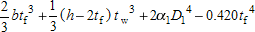
where:
| α 1 | 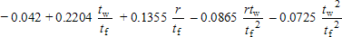 |
| D 1 | 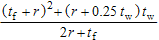 |
| b | is the width of the section |
| h | is the depth of the section |
| t f | is the flange thickness |
| t w | is the web thickness |
| r | is the root radius |
Parallel flange channels
For parallel flange channels, the warping constant (Iw ) and torsional constant (IT ) have been calculated as follows:
Iw = 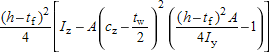
IT = 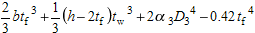
where:
| c z | is the distance from the back of the web to the centroidal axis |
| α 3 | =  |
| D 3 | = 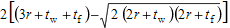 |
Note: The formula for the torsional constant (IT) is applicable to parallel flange channels only and does not apply to tapered flange channels.
Tapered flange channels
For tapered flange channels, section properties were calculated using expressions in reference [29].
Angles
For angles, the torsional constant (IT ) is calculated as follows:
IT = 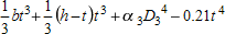
where:
| α 3 | =  |
| D 3 | =  |
3.2.7. Equivalent slenderness coefficient (ɸ) and monosymmetry index (ψ)
Angles
The buckling resistance moments for angles have not been included in the bending resistance tables of this website as angles are predominantly used in compression and tension only. Where the designer wishes to use an angle section in bending, EN 1993‑1‑1, §6.3.2 enables the buckling resistance moment for angles to be determined. The procedure is quite involved.
Therefore supplementary section properties have been included for angle sections in this website which enable the designer to adopt a much simplified method for determining the buckling resistance moment. The method is based on that given in BS 5950‑1:2000, Annex B.2.9.
The equivalent slenderness coefficient and the monosymmetry index have been tabulated to enable a designer to determine the buckling resistance moment of angles.
The equivalent slenderness coefficient (ɸa ) is tabulated for both equal and unequal angles. Two values of the equivalent slenderness coefficient are given for each unequal angle. The larger value is based on the major axis elastic section modulus (Wel,u ) to the toe of the short leg and the lower value is based on the major axis elastic section modulus to the toe of the long leg.
The equivalent slenderness coefficient (ɸa ) is calculated as follows:
ɸa = 
where:
| W el,u | is the elastic section modulus about the major axis u-u |
| g | =  |
| I v | is the second moment of area about the minor axis |
| I u | is the second moment of area about the major axis |
| A | is the area of the cross section |
| I T | is the torsional constant |
The monosymmetry index (ψa ) is calculated as follows:
ψa = 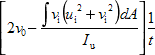
where:
| u i and v i | are the coordinates of an element of the cross-section |
| ν 0 | is the coordinate of the shear centre along the v-v axis, relative to the centroid |
| t | is the thickness of the angle |