Member resistance
4.1 Design strength
Light gauge steel sections include steel grades S350GD, S390GD, S420GD, S450GD, S550GD, S650GD & S700GD specified to EN 10346:2025 with design strengths of 350MPa,390MPa, 420MPa, 450MPa, 550MPa, 650MPa and 700MPa respectively. There is no reduction in yield strength with thickness of steel.
4.2 Cross section bending resistance, Mcy,Rd
The cross section bending resistance is determined in accordance with EN 1993-1-1.
4.3 Member bending resistance
The bending moment resistance of the member is determined in accordance with clause 6.1.4 of EN 1993-1-3. The effect of shear lag is taken into account according to EN 1993-1-5.
4.4 Lateral torsional buckling resistance
The non-dimensional slenderness is calculated as:

Mcr is calculated based on the gross cross section (CEN/TR1993-1-103) where

and
| E | is the Young modulus (E = 210000 N/mm2) |
| G | is the shear modulus (G = 80770 N/mm2) |
| Iz | is the second moment of area about the weak axis |
| It | is the torsion constant |
| Iw | is the warping constant |
| L | is the beam length between points which have lateral restraint |
| k | is the effective length factor specific to end rotation on plan (analogous to the ratio of the buckling length to the system length). k should be taken as not less than 1.0 unless it can be justified |
| kw | is the effective length factor specific to end warping. (typically taken as 1.0) |
| zg | is the distance between the point of load application and the shear centre. In the general case zg is positive for loads acting towards the shear centre from their point of application |
| zj | is the asymmetry factor. It is positive when the flange with the larger value of Iz is in compression at the point of the larger bending moment. Note zj is zero for the sigma sections. |
In the common case of normal support conditions at the ends (fork supports), k and kw are taken equal to 1.0.
C1, C2 and C3 are coefficients depending on the loading and end restraint conditions. See 'NCCI: Mono-symmetrical uniform members under bending and axial compression' SN030a-EN-EU [6]. (This NCCI is not specifically appropriate for Z sections, however, it is used as no other suitable documentation is available for light gauge steel sections. C2 has been kept constant at 0.454 as no other information is available.
Lateral torsional buckling values are determined in accordance with EN 1993-1-1:2005, Clause 6.3.2.2, for single span and double span beams undergoing uniformly distributed loading.
C1, C2 and C3 are presented in Tables 4.1 to 4.3.
Table 4.1 C factors for a single span beam experiencing wind uplift
| Sag rods | C1 | C2 | C3 |
| 0 | 1.127 | 0.454 | 0.525 |
| 1 | 1.77 | 0.454 | 0.94 |
| 2 | 1.0 | 0.454 | 1.0 |
Table 4.2 C factors for a double span beam experiencing wind uplift
| Sag rods | C1 | C2 | C3 |
| 0 | 1.77 | 0.454 | 0.94 |
| 1 | 1.77 | 0.454 | 0.94 |
| 2 | 1.40 | 0.454 | 0.99 |
Table 4.3 C factors for a double span beam experiencing downward loading (hogging moment at inner support)
| Sag rods | C1 | C2 | C3 |
| 0 | 1.77 | 0.454 | 0.94 |
| 1 | 2.33 | 0.454 | 0.68 |
| 2 | 2.05 | 0.454 | 0.85 |
CEN/TR1993-1-103 gives values for C1, C2, C3 according various load cases, various values of buckling factors.
4.5 Deflections
A check is required to show that the member is adequate at the serviceability limit state (SLS). For normal building applications, this involves checking the imposed load deflections against specified limits. Occasionally, the dynamic response of light steel floors will also need to be checked.
For the purpose of calculating deflections, the second moment of area should be calculated using equation

where:
| Igr | is the second moment of area of the gross cross section. |
| σgr | is the maximum compressive bending stress at SLS based on gross cross section properties. |
| I(σ)eff | is the second moment of area of the effective cross section calculated for a maximum stress σ ≥ σgr. |
For a simple supported single spanning beam the maximum deflection is given by δmax where
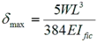
where:
| W | is the total uniformly distributed load on the beam. |
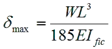
For a double equal span beam the maximum deflection δmax is given by
4.6 Resistance tables
Resistances are provided for single span and double span beam configurations for a range of beam spans. Resistances are provided at the Ultimate Limit State and the Serviceability Limit State. Loading comprises a uniformly distributed load along the beam acting in downward and upward directions.
4.7 Shear resistance, Vb,Rd
The shear resistance is determined in accordance with clause 6.1.5 of EN 1993-1-3.